+91 97244 57680
sales.zeelengineers@gmail.com
Mon - Sat, 9am - 7pm
+91 97244 57680
sales.zeelengineers@gmail.com
Mon - Sat, 9am - 7pm
| Accessories | ||
| Modulating Controller | : | 4 ~ 20 mA (Available on request) |
| Potentiometer Feedback | : | Available on request |
| Integral Starter unit | : | Available on request |
| Control Panel | : | Available on request |
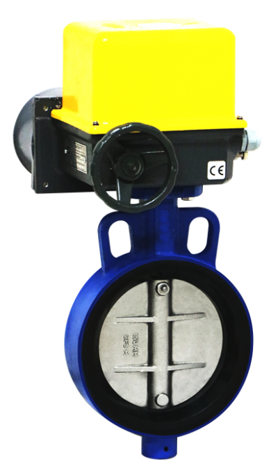
| Electrical Actuator Details | ||
| Manufacturer | : | Zeel engineers |
| Brand / Model | : | Zeel engineers / MOD |
| Characteristic | : | On – Off Type |
| Travel | : | 90 Degree |
| Indicator | : | Continuous Position Indicator |
| Phase | : | Single Phase |
| Power Supply | : | 220V AC, 50 Hz |
| Body Material | : | Aluminum Alloy |
| Ambient Temperature | : | 20°C ~ 80°C |
| Motor Insulation | : | Class F |
| Protection Class | : | IP – 67 Weather Proof |
| Manual Adjustment | : | Wrench Setting |
| Limit Switch | : | 1NO + 1NC output of 220V AC |
| Position Power Failure | : | Stay Put |
| Size Range | 1.1/2″ to 72″ |
| Construction Type | Double Eccentric Disc Design |
| Body | WCB/CF8/CF8M/CAST IRON |
| Disc | WCB/CF8/CF8M |
| Seat | PTFE (available EPDM/ Metal to Metal) |
| Shaft | AISI 41 0/304/31 6 |
| Plate Mounting | NAMUR Standard |
| Pressure Rating | ANSI 150 class /ANSI 300 Class (On Request) |
| End Connection | Wafer Sandwiched / Lug type (On Request) |
| Operating Temp. Range | -25°Cto1 80°C (Soft Seating) -25°C to600°C (Metal to Metal Seating) |
| Operation | Hand Lever, Worm Gear Box Pneumatic Actuated, Electrical Actuated |
| Size | Differential Pressure (AP) | |||
| 5 kg/cm2 | 10 kg/cm2 | 15 kg/cm2 | 20 kg/cm2 | |
| 1.1/2″ (40) | 0.8 | 1.0 | 1.2 | 1.5 |
| 2″ (50) | 0.9 | 1.2 | 1.5 | 1.7 |
| 2.1/2″ (65) | 1.6 | 2.2 | 2.4 | 3.0 |
| 3″ (80) | 3.0 | 3.4 | 4.2 | 5.0 |
| 4″ (100) | 4.0 | 4.6 | 5.4 | 6.4 |
| 5″ (125) | 5.8 | 8.0 | 9.5 | 11.5 |
| 6″ (150) | 9.0 | 11.5 | 12.5 | 14.5 |
| 8″ (200) | 14.0 | 17.5 | 24.0 | 28.0 |
| 10″ (250) | 23.5 | 26.5 | 28.0 | 30.0 |
| 12″ (300) | 32.0 | 36.0 | 40.0 | 50.0 |
| 14″ (350) | 50.0 | 65.0 | 83.5 | 108.5 |
| 16″ (400) | 69.4 | 94.5 | 120.0 | 160.0 |
| 18″ (450) | 95.5 | 128.0 | 157.2 | 205.0 |
| 20″ (500) | 122.5 | 193.3 | 210.0 | 293.4 |
| 24″ (600) | 213.3 | 293.4 | 366.7 | 440.1 |
| 26″ (650) | 265 | 35O | 400 | 510 |
| 28″ (700) | 300 | 395 | 480 | 595 |
| 30″ (750) | 321 | 420 | 519 | 617 |
| 32″ (800) | 481 | 630 | 780 | 920 |
| 36″ (900) | 518 | 663 | 850 | 992 |
| 40″ (1000) | 641 | 850 | 1060 | 1300 |
| 48″ (1200) | 850 | 1166 | 1485 | 1632 |
| Standards | Series 5500 (40 NB TO 600 NB) |
Series 5501 (650 NB TO 1200 NB) |
| Design and Manufacturing | API 609 CATAGORY B. | MSS SP-68 |
| Valve Face to Face Dimensions | API 609 CATAGORY B /ANSI B 16.10 | ISO 5752 SERIES 20, MSS SP – 68 |
| Flange Standard Conformity | ANSI B 16. 5 CLASS 150 | ASME / ANSI B 16.47 SERIES W |
| Inspection & Testing Standard | API 598 / ANSI FCI 70 -2 | API 598 / BS 6755 |
| Fire Safe Testing | API 607 | API 607 |
| Pressure Temperature Rating | ASME/ANSIB16.34 | ASME /ANSI B 16. 34 |
| VLV.SIZE | A | B | B1 | C | H | ØE | ØD | Weight |
| 1.1/2″ (40) | 42 | 46 | 29.5 | 59.5 | 144.5 | 38 | 82 | 1.600 |
| 2″ (50) | 45 | 46 | 29.5 | 68.5 | 163.5 | 50.8 | 95 | 2.200 |
| 2. 1/2″ (65) | 48 | 46 | 29.5 | 74.5 | 188 | 60.6 | 108 | 3.000 |
| 3″ (80) | 48 | 56 | 41.5 | 80 | 200 | 72 | 127 | 3.800 |
| 4″ (100) | 54 | 56 | 50 | 95 | 228 | 100 | 159 | 5.600 |
| 5″ (125) | 57 | 60 | 51 | 117 | 268 | 123 | 186 | 7.700 |
| 6″ (150) | 57 | 60 | 60 | 132 | 300 | 143 | 217 | 10.400 |
| 8″ (200) | 64 | 60 | 60 | 157 | 36.5 | 192 | 270 | 15.000 |
| 10″ (250) | 71 | 60 | 60 | 172 | 396 | 239 | 323 | 25.750 |
| 12″ (300) | 81 | 69.5 | 60 | 200 | 465 | 290 | 380 | 36.000 |
| 14″ (350) | 92 | 69.5 | 69.5 | 224 | 534 | 335 | 406 | 46.900 |
| 16″ (400) | 102 | 86.5 | 86.5 | 250.5 | 592 | 387.5 | 490 | 66.850 |
| 18″ (450) | 114 | 86.5 | 86.5 | 355 | 745 | 425 | 540 | 117.000 |
| 20″ (500) | 127 | 112.5 | 112.5 | 384 | 805 | 475 | 594 | 146.500 |
| 24″ (600) | 154 | 112.5 | 112.5 | 460 | 960 | 560 | 705 | 290.000 |
| 26″ (650) | 165 | – | – | 455.72 | 938.5 | 608 | 755 | 360.000 |
| 28″ (700) | 165 | – | – | 480 | 988 | 661.5 | 810 | 390.000 |
| 30″ (750) | 190 | – | – | 512 | 1047 | 696 | 855 | 475.000 |
| 32″ (800) | 190 | – | – | 550.2 | 1126.4 | 755 | 913 | 524.000 |
| 36″ (900) | 203 | – | – | 605 | 1255 | 864 | 1032 | 675.000 |